

ESP32-WROOM-32 Datasheet Explained: Specifications, Pinout & Performance
ESP32-WROOM-32 Introduction
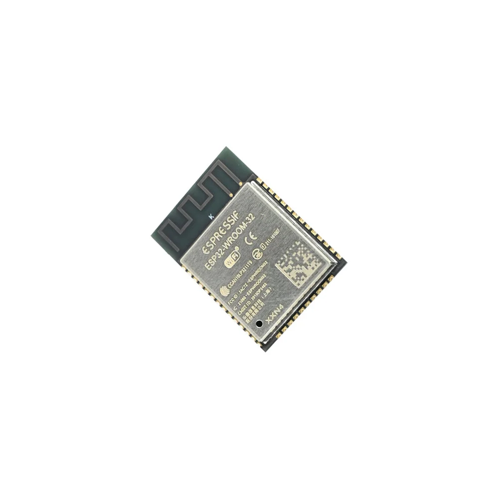
The ESP32-WROOM-32 is one of the most popular Wi-Fi and Bluetooth modules, widely used in IoT applications, embedded systems, and industrial automation. Designed by Espressif Systems, it provides high performance, low power consumption, and a variety of interfaces for different applications.
In this guide, we’ll dive into the ESP32-WROOM-32 datasheet, covering its specifications, pinout, and performance metrics to help you understand its capabilities better.
ESP32-WROOM-32 Key Specifications
|
Feature |
Specification |
|
Processor |
Dual-core Tensilica Xtensa LX6 @ 240 MHz |
|
Wireless Connectivity |
Wi-Fi (802.11 b/g/n), Bluetooth 4.2 (BLE & Classic) |
|
Flash Memory |
4MB (default), up to 16MB available |
|
SRAM |
520 KB internal, 8MB external PSRAM supported |
|
Operating Voltage |
3.3V |
|
GPIO Pins |
34 programmable GPIOs |
|
Analog Inputs |
18 channels (ADC1 & ADC2) |
|
Digital Interfaces |
UART, SPI, I2C, I2S, PWM |
|
Power Consumption |
Ultra-low power (5 µA in deep sleep) |
|
Security Features |
AES encryption, Secure Boot, Flash Encryption |
The ESP32-WROOM-32 is an ideal module for IoT projects, smart home devices, robotics, and industrial applications, thanks to its power efficiency and versatile connectivity options.
ESP32-WROOM-32 Pinout Overview
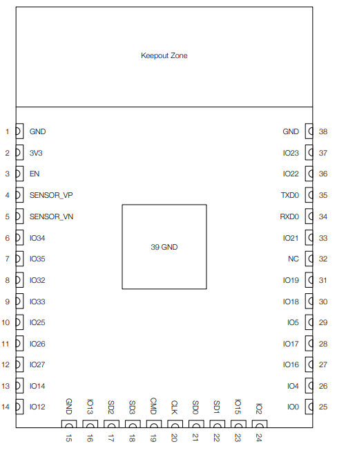
Understanding the pinout of the ESP32-WROOM-32 module is crucial for properly interfacing it with external components. Below is the detailed pinout table.
ESP32-WROOM-32 Pinout
|
Pin Number |
Pin Name |
GPIO Number |
Functionality |
|
1 |
GND |
- |
Ground (Common connection for all circuits) |
|
2 |
3V3 |
- |
3.3V Power Supply for the module |
|
3 |
EN |
- |
Enable Pin (Needs to be HIGH to power up the chip) |
|
4 |
SENSOR_VP |
GPIO36 |
Analog Input (Used for sensors, ADC1 Channel 0) |
|
5 |
SENSOR_VN |
GPIO39 |
Analog Input (Used for sensors, ADC1 Channel 3) |
|
6 |
IO34 |
GPIO34 |
Analog Input (ADC1 Channel 6, No Output capability) |
|
7 |
IO35 |
GPIO35 |
Analog Input (ADC1 Channel 7, No Output capability) |
|
8 |
IO32 |
GPIO32 |
General Purpose I/O (Can be used as ADC, Touch Sensor) |
|
9 |
IO33 |
GPIO33 |
General Purpose I/O (Can be used as ADC, Touch Sensor) |
|
10 |
IO25 |
GPIO25 |
DAC Output (Can generate analog signals, ADC2 CH8) |
|
11 |
IO26 |
GPIO26 |
DAC Output (Can generate analog signals, ADC2 CH9) |
|
12 |
IO27 |
GPIO27 |
General Purpose I/O, Touch Sensor, Ethernet RX |
|
13 |
IO14 |
GPIO14 |
General Purpose I/O, SPI Clock, PWM, Touch Sensor |
|
14 |
IO12 |
GPIO12 |
General Purpose I/O, SPI Data, Touch Sensor |
|
15 |
GND |
- |
Ground (Common connection) |
|
16 |
IO13 |
GPIO13 |
General Purpose I/O, SPI Data, Touch Sensor |
|
17 |
SHD/SD2 |
GPIO9 |
Used for Flash Memory (Not Recommended for GPIO) |
|
18 |
SWP/SD3 |
GPIO10 |
Used for Flash Memory (Not Recommended for GPIO) |
|
19 |
SCS/CMD |
GPIO11 |
Used for Flash Memory (Not Recommended for GPIO) |
|
20 |
SCK/CLK |
GPIO6 |
Used for Flash Memory (Not Recommended for GPIO) |
|
21 |
SDO/SD0 |
GPIO7 |
Used for Flash Memory (Not Recommended for GPIO) |
|
22 |
SDI/SD1 |
GPIO8 |
Used for Flash Memory (Not Recommended for GPIO) |
|
23 |
IO15 |
GPIO15 |
General Purpose I/O, SPI, PWM, Touch Sensor |
|
24 |
IO2 |
GPIO2 |
General Purpose I/O, Boot Mode Selection Pin |
|
25 |
IO0 |
GPIO0 |
General Purpose I/O, Boot Mode Selection Pin |
|
26 |
IO4 |
GPIO4 |
General Purpose I/O, ADC2 Channel 0, Touch Sensor |
|
27 |
IO16 |
GPIO16 |
UART Communication, General Purpose I/O |
|
28 |
IO17 |
GPIO17 |
UART Communication, General Purpose I/O |
|
29 |
IO5 |
GPIO5 |
General Purpose I/O, SPI Chip Select |
|
30 |
IO18 |
GPIO18 |
General Purpose I/O, SPI Clock |
|
31 |
IO19 |
GPIO19 |
General Purpose I/O, SPI Data |
|
32 |
NC |
- |
Not Connected (No Function) |
|
33 |
IO21 |
GPIO21 |
General Purpose I/O, I2C SDA (Data Line) |
|
34 |
RXD0 |
GPIO3 |
UART Receive Pin (Used for serial communication) |
|
35 |
TXD0 |
GPIO1 |
UART Transmit Pin (Used for serial communication) |
|
36 |
IO22 |
GPIO22 |
General Purpose I/O, I2C SCL (Clock Line) |
|
37 |
IO23 |
GPIO23 |
General Purpose I/O, SPI Data |
|
38 |
GND |
- |
Ground (Common connection) |
Below are some key notes on the ESP32-WROOM-32 pinout:
-
Power & Ground:
-
Pin 2 (3V3) provides the 3.3V power supply, and multiple GND pins (e.g., Pin 1, 15, 38) are available for a common ground reference.
-
Module Activation:
-
Pin 3 (EN) is used as the enable pin. The chip powers up only when this pin is held HIGH.
-
Analog Inputs:
-
Several pins support analog input, including dedicated sensor pins like SENSOR_VP (GPIO36) and SENSOR_VN (GPIO39), as well as other GPIOs (e.g., IO34 and IO35) that serve as ADC inputs but cannot output digital signals.
-
Digital I/O and Multipurpose Functions:
-
Many pins are versatile and can function as general-purpose digital I/O, PWM outputs, SPI, I2C, or UART communication lines. For example, IO32 and IO33 can also be used for touch sensing or ADC functions.
-
DAC and ADC Channels:
-
Pins such as IO25 (GPIO25) and IO26 (GPIO26) are equipped with DAC capabilities, while others serve as ADC channels, making them suitable for sensor interfacing.
-
Reserved Flash Memory Pins:
-
Some pins (e.g., SHD/SD2, SWP/SD3, SCS/CMD, SCK/CLK, SDO/SD0, SDI/SD1) are primarily used for flash memory and are not recommended for general GPIO usage. Altering these might interfere with the module’s flash operations.
-
Communication Protocols:
-
Dedicated pins for UART (e.g., RXD0, TXD0), SPI (e.g., IO14, IO12, IO15), and I2C (e.g., IO21, IO22) are provided to facilitate easy communication with external devices.
-
IO0 and IO2 also play a role in boot mode selection, which is crucial during the startup process.
-
Other Special Features:
-
Some pins have additional capabilities such as touch sensing and can be reconfigured for specific tasks.
-
NC (Not Connected) indicates a pin that is not used and should be left unconnected.
ESP32-WROOM-32 Performance & Features
-
High Processing Power: Dual-core Xtensa LX6 processor (240 MHz) enables fast data handling and execution.
-
Wi-Fi & Bluetooth Integration: Supports Wi-Fi 802.11 b/g/n and Bluetooth 4.2 (Classic & BLE) for seamless wireless connectivity in various applications.
-
Ultra-Low Power Consumption: Deep sleep mode can draw as little as 5 µA, making the module ideal for battery-powered and energy-efficient applications.
-
Multiple ADC & DAC Channels: Offers 18 ADC inputs and 2 DAC outputs for precise analog signal measurement and generation, enabling integration with a variety of sensors.
-
Advanced Security Features: Equipped with AES encryption, Secure Boot, and Flash Encryption, ensuring secure operations in IoT deployments.
-
Rich Communication Interfaces: Supports UART, SPI, I2C, I2S, and PWM, allowing connectivity with a wide range of peripherals and sensors.
-
Expandable Memory Options: Built-in 4MB Flash with support for up to 16MB Flash and 8MB external PSRAM, accommodating complex applications and data storage needs.
-
Built-in Touch Sensor Support: Integrated touch sensor functionality enhances interactive applications without needing additional hardware.
-
Real-Time Clock (RTC) Functionality: Ensures accurate timekeeping in low-power modes, which is crucial for scheduling and energy management in IoT systems.
-
Robust Industrial-Grade Performance: Designed to operate reliably across various environments, making it suitable for both consumer and industrial applications.
-
Flexible Development Ecosystem: Compatible with popular development platforms such as Arduino IDE, ESP-IDF, and MicroPython, providing versatility for both beginners and experienced developers.
Conclusion
The ESP32-WROOM-32 is a highly versatile module that combines high performance, extensive connectivity options, and power efficiency. Whether you are developing an IoT system, industrial automation, or robotics project, this module offers all the necessary features to get started.
To purchase ESP32-WROOM-32, check out Electronify India!
ESP32-WROOM-32 FAQs
Q1: How many GPIOs are available in ESP32-WROOM-32?
Ans: It has 34 programmable GPIOs, with some dedicated ADC, DAC, and communication interfaces.
Q2: What is the power consumption of ESP32-WROOM-32?
Ans: In deep sleep mode, it consumes as low as 5 µA, making it ideal for battery-powered applications.
Q3. How do I use the ESP32-WROOM-32 in my projects?
Ans: To integrate the ESP32-WROOM-32 into your projects:
-
Development Environment: Set up the Arduino IDE or ESP-IDF (Espressif IoT Development Framework) for programming.
-
Programming: Write your code using the chosen development environment and upload it to the module via a USB or serial connection.
-
Power Supply: Ensure a stable 3.3V power supply, as the module operates at this voltage.
-
Peripherals: Utilize the available GPIO pins for connecting sensors, actuators, and other components.
Q4. What are the GPIO pinout details of the ESP32-WROOM-32?
Ans: The ESP32-WROOM-32 offers 34 GPIO pins with various functions:
-
GPIOs 0-19: Can be used for digital I/O, PWM, SPI, I2C, UART, and more.
-
GPIOs 34-39: Input-only pins, suitable for analog inputs (ADC).
-
GPIOs 21 and 22: Default I2C SDA and SCL, respectively.
-
GPIOs 1 and 3: Default UART TX and RX, respectively.
For detailed pinout diagrams and specific functions, refer to the official datasheet.
Q5. How do I power the ESP32-WROOM-32?
Ans: The ESP32-WROOM-32 operates at 3.3V. Ensure a stable 3.3V power supply, as supplying higher voltages can damage the module. It's advisable to use a voltage regulator to provide a consistent 3.3V output.
Q6. Can the ESP32-WROOM-32 run both Wi-Fi and Bluetooth simultaneously?
Ans: Yes, the ESP32-WROOM-32 supports concurrent Wi-Fi and Bluetooth operations, allowing for versatile communication options in your projects.
Q7. What are the power consumption characteristics of the ESP32-WROOM-32?
Ans: The ESP32-WROOM-32 is designed for low power consumption:
-
Active Mode: Approximately 160 mA during Wi-Fi transmission.
-
Deep Sleep Mode: As low as 5 µA, making it suitable for battery-powered applications.
Q8. How do I program the ESP32-WROOM-32?
Ans: Programming the ESP32-WROOM-32 involves:
-
Development Environment: Install the Arduino IDE or ESP-IDF.
-
Board Selection: Choose the appropriate ESP32 board in the IDE.
-
Programming: Write your code and upload it to the module via USB or serial connection.
Q9. What are the limitations of the ESP32-WROOM-32?
Ans: While the ESP32-WROOM-32 is versatile, consider the following limitations:
-
GPIO Pin Restrictions: Some pins have specific functions and may not be used for general I/O.
-
Power Supply: Requires a stable 3.3V supply; higher voltages can damage the module.
-
Flash Memory: Limited to the onboard flash size; external storage options are available but may require additional components.
Q10. Where can I buy genuine ESP32-WROOM-32 modules?
Ans: When purchasing the ESP32-WROOM-32, it’s important to buy from a genuine and trusted supplier to ensure quality and reliability. One such reliable source is Electronify India, a trusted supplier of electronic components and modules, including the ESP32-WROOM-32.
Buying from authentic suppliers ensures that you receive original products with full support, warranties, and technical assistance. Be cautious of counterfeit or substandard products available from unauthorised sellers, as they may affect your project’s performance.
